Flameproof Smart Gas Detector & Transmitter
HSN Code: 90271000

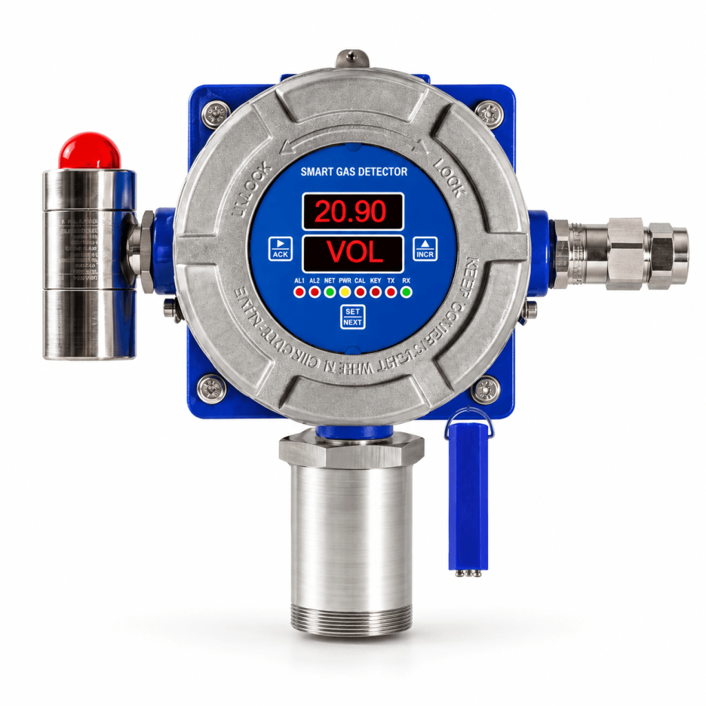
The Chromgate Flameproof Smart Gas Detector & Transmitter is designed for continuous monitoring of oxygen, toxic, combustible and volatile organic compound gases in hazardous industrial environments.

Its hot-swappable smart sensor technology, digital display, configurable alarm outputs and optional RS-485 communication provide reliable gas-leak detection with convenient installation, programming and maintenance.

Key Features
  • Suitable for oxygen, toxic, combustible and VOC gas detection
  • Electrochemical, catalytic/pellistor, NDIR, PID and solid-state sensor options
  • Hot-swappable, smart pluggable sensor module
  • Detection units available in PPM, % v/v, % LEL and mg/m³
  • Two-line, four-digit LED display
  • Eight status-indication LEDs
  • Standard configurable 4–20 mA output
  • Optional 0–10 V, 0–5 V or 0–1 V output
  • Optional isolated RS-485 communication with Modbus RTU protocol
  • Two independently configurable alarm setpoints
  • Optional STEL and TWA settings for toxic gases and VOCs
  • Non-intrusive programming using a magnetic wand
  • Password-protected configuration
  • On-board alarm acknowledgement
  • Sensor-open, over-range, sensor-replacement, calibration-due, calibration-failure and mA-loop-open indications
  • Two alarm relays and one fail-safe relay
  • Optional PESO-certified hooter-cum-flasher
Technical Specifications
Parameter Specification
Product type Fixed Flameproof Smart Gas Detector/Transmitter
Detection method Diffusion
Sensor technologies Electrochemical, Catalytic/Pellistor, NDIR, PID or Solid-State
Gases detected Oxygen, toxic gases, combustible gases and VOCs
Display Two-line, four-digit, 8 mm seven-segment LED display
Status indicators Eight LED indicators
Response time Less than 15 seconds, depending on the selected gas
Standard output Configurable 4–20 mA
Current-output accuracy ±0.125% of full scale
Optional voltage output 0–10 V, 0–5 V or 0–1 V
Optional communication Isolated RS-485 with Modbus RTU
Alarm functions Two configurable alarm levels with latch/non-latch facility
Relay outputs Two alarm relays and one fail-safe relay
Supply voltage 18–36 V DC; typically 24 V DC
Power consumption Less than 3.6 W
Cable size 2.5 mm² flexible or armoured shielded cable
Configuration Magnetic wand without opening the enclosure
Operating temperature -20°C to +60°C
Storage temperature -30°C to +70°C
Humidity Less than 95% RH, non-condensing
Protection class IP66/IP68, depending on configuration
Enclosure material Cast aluminium alloy LM6
Sensor-holder material SS 316
Cable gland Double-compression cable gland
Cable entry M20 × 1.5
Mounting options Wall, stand or pipe mounting
Approximate dimensions* 225 mm H × 270 mm W × 120 mm D
Approximate weight* 2.7 kg

*Dimensions and weight are stated for the configuration fitted with the sensor holder and hooter-cum-flasher.

Sensor Accuracy
Sensor technology Calibration accuracy
Electrochemical ±2% of full scale
Catalytic/Pellistor ±2% of full scale
NDIR – CH₄, CO₂ or C₃H₈ ±10% of applied gas
PID: 0–5,000 PPM ±10% of applied gas
PID: 0–1,000 PPM ±5% of applied gas
PID: 0–50 PPM ±3% of applied gas
Available Gas Categories
Oxygen and Nitrogen
  • Oxygen: 0–25% v/v
  • Oxygen: 0–100% v/v
  • Nitrogen: 0–100% v/v
Toxic Gases

Available gases include:

  • Ammonia
  • Bromine
  • Carbon monoxide
  • Chlorine
  • Ethylene oxide
  • Hydrogen
  • Hydrogen bromide
  • Hydrogen chloride
  • Hydrogen cyanide
  • Hydrogen fluoride
  • Hydrogen sulphide
  • Ozone
  • Phosphine
  • Nitrogen dioxide
  • Nitric oxide
  • Sulphur dioxide
NDIR Gases
  • Carbon dioxide
  • Methane
  • Propane/LPG
PID/VOC Detection
  • Isobutylene
  • Other compatible volatile organic compounds
Combustible Gases

Detection is available for numerous combustible gases in the 0–100% LEL range, including:

  • Acetone
  • Acetylene
  • Ammonia
  • Butane/n-butane
  • Carbon monoxide
  • Ethanol
  • Ethyl acetate
  • Ethylene
  • Hexane
  • Hydrogen
  • Isopropanol
  • Methane
  • Methanol
  • N-heptane
  • N-pentane
  • Propane/LPG
  • Toluene
  • Unleaded petrol
  • CNG, LNG, LPG and natural gas

Note: The exact measuring range, resolution and sensor technology should be selected according to the target gas and application.

Approvals and Compliance
  • Flameproof protection: Ex db IIC T6 Gb
  • Dust ignition protection: Ex tb/tc IIIC T85°C Db/Dc
  • Intrinsic safety protection: Ex ia IIC T6 Ga
  • Ingress protection: IP66/IP68
  • EMI/EMC compliance: EN 50270
  • PESO/CMFR-approved enclosure and cable-gland options
Applications
  • Refineries and petrochemical plants
  • Chemical-processing plants
  • Fertilizer plants
  • Gas-cylinder banks and storage areas
  • Gas-pipeline projects
  • Cold-storage facilities
  • Sewage-treatment plants
  • Power and industrial plants
  • Chemical-storage areas
  • Burner and furnace areas
  • Paint shops
  • Pulp and paper plants
  • Offshore drilling and processing platforms
  • Confined spaces
  • Ambient and stack monitoring
  • Gas-metering stations and skids
Optional Accessories
  • Certified 24 V DC power supply
  • Canopy and mounting stand
  • Gas-calibration kit
  • PESO-certified hooter-cum-flasher
  • Gas-sampling and conditioning system
  • RS-485-to-USB or RS-232 converter
  • Ethernet converter
  • PC-based SCADA software and modem
Standard Deliverables
  • Test and calibration certificate
  • Reference calibration-gas certificate
  • Operation and maintenance manual
  • Standard mounting hardware
Multi-Channel Gas Monitoring System
HSN Code: 90271000

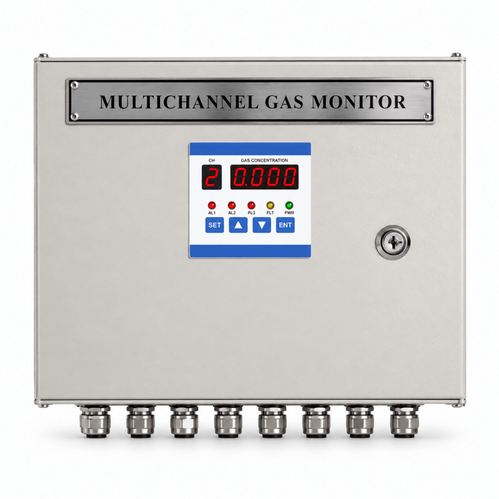
The Chromgate Multi-Channel Gas Monitoring System is a centralized control and alarm panel designed to continuously monitor signals received from multiple fixed gas detectors installed in hazardous or process areas.

The system supports oxygen, toxic and combustible-gas transmitters with standard 4–20 mA outputs. It sequentially displays individual gas concentrations and provides configurable high- and low-level alarms, common relay outputs and optional communication, data-logging and SCADA integration.

Key Features
  • Available in 2-, 4-, 6- and 8-channel configurations
  • Accepts standard 4–20 mA signals from two-wire or three-wire gas transmitters
  • Compatible with oxygen, toxic and combustible-gas detectors
  • Sequential scanning of each connected channel
  • Displays readings in PPM, PPB, % v/v or % LEL
  • User-programmable measuring range and resolution
  • Two independent alarm setpoints for every channel
  • Configurable low, high, high-high and low-low alarm actions
  • Programmable latching and non-latching alarms
  • Individual channel skip and continuous hold functions
  • Open-loop and sensor-break indication
  • Field-offset adjustment for reading correction
  • Front-panel programming and alarm acknowledgement
  • Common alarm relay outputs
  • Optional individual relay output for each channel
  • Optional data logging, printer interface and PC software
  • Optional RS-232 or RS-485 communication with Modbus RTU
  • Suitable for wall or stand mounting
  • Designed for installation in a safe area or control room
Technical Specifications
Parameter Specification
Product type Multi-Channel Gas Monitoring and Alarm Control Panel
Channel configurations 2, 4, 6 or 8 channels
Maximum inputs Up to 8 gas-transmitter inputs
Input signal 4–20 mA from two-wire or three-wire gas transmitters
Compatible detectors Oxygen, toxic and combustible-gas transmitters
Measuring range 0–9999, programmable by the user
Display units PPM, PPB, % v/v or % LEL
Resolution 0.01, 0.1 or 1, user programmable
Process-value display Four-digit, 13 mm high red LED
Channel display Single-digit, 13 mm high red LED
Alarm indication Eight red LEDs for AL1 and AL2 status
Alarm setpoints Two independent setpoints for each channel
Alarm modes Low, high, high-high, low-low and high inverse
Relay configuration Two common alarm relay outputs
Relay contacts 1 NO/COM/NC contact for each common alarm relay
Relay rating 230 V AC, 5 A
Relay operation Programmable latch or non-latch
Channel skip Individual channel skip from the front panel
Channel hold Continuous hold facility for a selected channel
Scan time 1–59 seconds, user programmable
Programming controls MODE, SHIFT, INC, ENT and PRN/ACK keys
Measurement accuracy ±0.5% of full-scale value
Power supply 100–270 V AC, ±10%
Transmitter cable 1.5 mm², two- or three-core flexible or armoured shielded cable
Operating temperature 0°C to 50°C
Relative humidity Below 95% RH, non-condensing
Panel protection IP50
Enclosure material Metal-sheet enclosure
Enclosure colour Siemens Grey
Cable glands Thermoplastic IP65 cable glands
Cable clamping range 2.5–6.5 mm
Mounting Wall or stand mounting
Dimensions 300 mm H × 320 mm W × 125 mm D
Approximate weight 6 kg
Alarm and Control Functions

The system provides two independently programmable alarm setpoints for each monitoring channel.

Available functions include:

  • Low alarm
  • High alarm
  • High-high alarm
  • Low-low alarm
  • High inverse alarm
  • Latching or non-latching operation
  • Common alarm-relay indication
  • Front-panel alarm acknowledgement
  • Optional individual relay for each channel
  • Optional grouped relay outputs
Communication and Monitoring Options

The following functions can be provided as optional configurations:

  • Isolated RS-232 communication
  • Isolated RS-485 communication
  • Modbus RTU protocol
  • Data-logging facility
  • PC-based SMART LOG or SCADA software
  • Online gas-concentration graphs
  • Historical data reports
  • Printer interface
  • Ethernet or intelligent modem connectivity
  • Cloud-based remote monitoring, subject to selected configuration
Optional Accessories
  • CE-certified 24 V DC power supply
  • Two- or three-core transmission cables
  • Gas-calibration kit in 0.5, 1, 3 or 10-litre capacity
  • Flameproof or non-flameproof hooter
  • Hooter-cum-flasher
  • Chart recorder
  • RS-485-to-USB converter
  • RS-232 converter
  • PC-based SCADA or SMART LOG software
  • Four- or eight-channel annunciator panel
  • Gas transmitters
  • Individual or grouped channel relays
  • Industrial communication modem
System Configuration

The typical system comprises:

  1. Fixed gas detectors installed in the hazardous or monitored area
  2. Signal cables connecting each detector to the control panel
  3. Multi-channel monitoring panel installed in the safe area or control room
  4. Audible and visual alarm devices
  5. Optional communication converter and monitoring computer
  6. Optional SCADA, data-logging or remote-monitoring system

The catalogue indicates a maximum transmitter-to-panel cable distance of approximately 1,000 metres, subject to cable specification, installation conditions and transmitter requirements.

Applications
  • Chemical and petrochemical plants
  • Refineries
  • Oil and gas facilities
  • Gas-cylinder banks
  • Gas-pipeline projects
  • Gas-metering stations
  • Chemical-storage areas
  • Fertilizer plants
  • Power and industrial plants
  • Pulp and paper plants
  • Sewage-treatment plants
  • Paint shops
  • Burner and furnace areas
  • Heat-treatment plants
  • Offshore drilling and processing platforms
  • Bullet yards and gas-storage yards
  • Coal mines and confined areas
  • Stack-monitoring applications
  • Automotive industries
  • Acid, alkali and dye-manufacturing plants
Important Approval Clarification

Compatible with approved hazardous-area gas transmitters. Detector certifications, enclosure protection and approvals depend on the selected field-detector model. The multi-channel control panel is intended for installation in a safe area or control room.