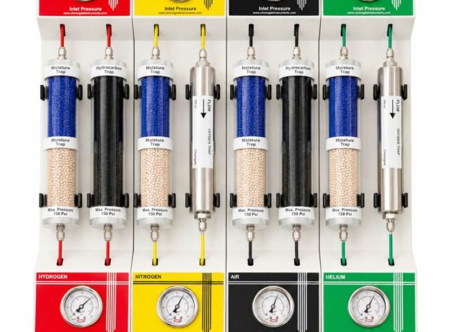
Chromgate gas control boxes provide localized pressure regulation, monitoring and isolation for GC, AAS, ICP and other laboratory instruments.
Laboratory Gas Control Box for Pressure Regulation and Monitoring
Analytical instruments require gases to be supplied at stable and controlled pressures. When a main cylinder regulator, manifold or gas purification panel is located away from the instrument, operators may need a convenient local point for monitoring and adjusting the final gas pressure.
The Chromgate Laboratory Gas Control Box is a compact, wall-mounted system designed to provide localized gas-pressure regulation, pressure indication and flow isolation near analytical instruments and laboratory points of use.
Available in single-line and multi-line configurations, the Gas Control Box can be customized according to the gases, pressure ranges, connection sizes, instrument requirements and installation layout.
What Is a Laboratory Gas Control Box?
A Gas Control Box is installed in the downstream section of a laboratory gas-distribution system, usually near the instrument or designated gas outlet.
Depending on the selected configuration, it may include:
- Inlet pressure gauge
- Outlet pressure gauge
- Adjustable pressure regulator
- Press-to-lock adjustment knob
- On/Off isolation valve
- SS-316 internal tubing
- Compatible compression fittings
- Gas-specific identification labels
- Wall-mounted protective enclosure
The unit provides operators with a clearly identified local control point without requiring routine access to the cylinder-storage or manifold area.
Purpose of a Gas Control Box
A laboratory gas system may begin at a cylinder, cylinder bank, manifold or automatic changeover unit. Gas is then routed through tubing to the analytical laboratory.
Although the primary cylinder regulator reduces the high cylinder pressure, a local Gas Control Box can provide secondary or point-of-use adjustment near the instrument.
Its principal functions are:
- Monitoring incoming gas pressure
- Adjusting downstream pressure
- Providing a visible pressure indication
- Isolating the gas supply locally
- Organizing multiple gas controls
- Identifying individual gas services
- Supporting convenient operation and maintenance
The exact configuration should be selected according to the overall pressure-control philosophy of the installation.
Main Components
Pressure Gauges
Pressure gauges provide visual indication of the gas pressure at specified points in the system.
Depending on the selected model, the Gas Control Box may have:
- One gauge for outlet pressure
- Separate inlet and outlet gauges
- Individual gauges for each gas line
The gauge range should be selected so that the normal operating pressure falls within a clearly readable portion of the scale.
Adjustable Pressure Regulator
The pressure regulator reduces and controls the downstream gas pressure supplied to the instrument.
Chromgate Gas Control Boxes can be fitted with an adjustable regulator featuring a press-to-lock knob. After the required pressure is set, the knob can be locked to reduce the possibility of accidental adjustment.
The regulator must be selected according to:
- Gas type
- Inlet pressure
- Required outlet pressure
- Flow capacity
- Material compatibility
- Connection size
- Required pressure stability
Isolation Valve
An On/Off valve allows the operator to isolate the downstream supply near the instrument.
Local isolation is useful during:
- Instrument shutdown
- Planned maintenance
- Tubing inspection
- Equipment relocation
- Leak testing
- Emergency response according to the site procedure
The valve should remain readily accessible and clearly identified.
Internal Tubing and Fittings
SS-316 tubing and compatible compression fittings can be used within the enclosure to provide a clean and organized gas path.
All wetted components must be compatible with the intended gas, pressure and service conditions.
Gas Identification Labels
Each gas line should have a clear and durable label. Colour coding can provide additional identification but should not replace the written gas name.
Identification should remain consistent from the cylinder source through the manifold, tubing route, Gas Control Box and instrument connection.
Available Configurations
Single-Line Gas Control Box
A single-line box is suitable for one gas service or one dedicated instrument connection.
It provides a compact solution for applications where one gas needs local pressure regulation and isolation.
Two-Line Gas Control Box
A two-line box accommodates two independent gases in one enclosure. Each gas line can include its own gauge, regulator, valve and label.
Three- and Four-Line Gas Control Boxes
Three- and four-line arrangements are useful for analytical instruments that require several gases or for multiple nearby points of use.
The enclosure dimensions and internal arrangement should provide sufficient spacing for clear gauge reading, convenient regulator operation and maintenance access.
Customized Configurations
Custom units can be developed according to:
- Number of gases
- Available wall space
- Pressure ranges
- Connection sizes
- Instrument specifications
- Valve requirements
- Labelling requirements
- Internal tubing material
- Site or project specifications
Gas Compatibility
A Gas Control Box may be configured for compatible laboratory gases such as:
- Nitrogen
- Hydrogen
- Helium
- Zero air
- Oxygen
- Argon
- Carbon dioxide
- Acetylene
- Nitrous oxide
- Ammonia
- Other laboratory gases
The gas list should not be interpreted as universal compatibility for one standard component arrangement. Regulators, gauges, valves, tubing, fittings and seals must be selected for the specific gas.
Flammable, oxidizing, toxic, corrosive and reactive gases require additional engineering and safety consideration.
Applications
Chromgate Gas Control Boxes can be used with:
- Gas Chromatographs
- GC-MS systems
- Atomic Absorption Spectrometers
- ICP-OES instruments
- ICP-MS instruments
- HR-ICP-MS instruments
- TOC analysers
- Laboratory reactors
- Gas analysers
- Research equipment
- Quality-control instruments
- Compatible industrial gas points
They can also be used as local control stations within centralized laboratory gas-distribution systems.
Gas Control Box vs Gas Purification Panel
A Gas Control Box and a Gas Purification Panel perform related but different functions.
A Gas Purification Panel normally focuses on:
- Removing specified contaminants
- Regulating gas pressure
- Monitoring inlet and outlet conditions
- Providing purification traps
A Gas Control Box normally focuses on:
- Local pressure adjustment
- Pressure monitoring
- Isolation near the instrument
- Organized point-of-use control
A complete installation may use both. The purification panel can be located upstream, while the Gas Control Box is installed closer to the analytical instrument.
Gas Control Box vs On/Off Valve Box
An On/Off Valve Box mainly provides local isolation. It typically does not offer the same level of pressure regulation and monitoring as a Gas Control Box.
Choose a Gas Control Box when local pressure adjustment or pressure indication is required. Choose an On/Off Valve Box when only local gas isolation is required.
Installation Guidelines
The Gas Control Box should be installed at a practical height and location where:
- Gauges are easy to read
- Regulators are accessible
- Valves can be operated safely
- Instrument connections are reasonably short
- Tubing is properly supported
- Maintenance can be performed
- Gas labels remain visible
- The box is protected from accidental impact
Tubing should be routed using compatible supports, clamps or casing-capping. Unnecessary joints should be minimized.
The installation must be checked for leakage before the gas is supplied to the instrument.
Information Required for Selection
To select the appropriate Gas Control Box, provide:
- Instrument make and model
- Number of gases
- Gas names
- Upstream supply pressure
- Required outlet pressure
- Required flow rate
- Number of control lines
- Inlet and outlet connection sizes
- Tubing material and size
- Distance from the source
- Mounting location
- Required valve type
- Applicable technical specifications
This information helps prevent undersized regulators, unsuitable gauge ranges and incompatible components.
Operation and Maintenance
Before operating the Gas Control Box:
- Confirm that all gas labels are correct.
- Verify that the regulator is in the appropriate starting position.
- Open the upstream supply according to the approved procedure.
- Open the isolation valve gradually.
- Adjust the outlet pressure while observing the gauge.
- Lock the regulator knob where applicable.
- Confirm stable pressure at the instrument.
Routine inspection should include:
- Checking gauges for damage
- Inspecting tubing and fittings
- Verifying valve operation
- Checking regulator performance
- Testing for leakage
- Confirming labels remain legible
- Monitoring for pressure instability
- Recording maintenance activity
The system should be isolated and depressurized before maintenance.
Benefits of a Chromgate Gas Control Box
A properly configured Gas Control Box offers:
- Local pressure regulation
- Clear pressure indication
- Convenient gas isolation
- Organized gas-line controls
- Reduced operator access to the cylinder area
- Clear gas identification
- Compact wall-mounted installation
- Single-line and multi-line options
- Compatibility with centralized gas systems
- Customization for analytical instruments
The operational performance depends on correct selection, installation, gas quality and maintenance.
Frequently Asked Questions
Does a Gas Control Box purify the gas?
A standard Gas Control Box primarily regulates, monitors and isolates the gas. Purification traps can be installed separately upstream or incorporated only when specifically included in the selected design.
Where should the Gas Control Box be installed?
It is generally installed near the analytical instrument at a location where the gauges, regulators and valves are easy to access.
Can one box control several gases?
Yes. Multi-line boxes can accommodate two, three, four or another agreed number of independently controlled gas lines.
Can the inlet and outlet connections be customized?
Yes. Connection types and sizes can be selected according to the tubing, instrument and project requirements.
Is SS-316 internal tubing available?
Yes. SS-316 tubing can be provided, subject to the selected model and gas compatibility.
Is the box suitable for hydrogen?
It can be configured for hydrogen using appropriately selected compatible components. The complete installation must follow applicable flammable-gas safety requirements.
What information is needed for a quotation?
Provide the gas names, number of lines, inlet pressure, required outlet pressure, flow rate, connection sizes, instrument model, quantity and project location.
Related Products
A Gas Control Box may be used with:
- Gas purification panels
- Cylinder regulators
- Manifold systems
- Automatic changeover systems
- On/Off valve boxes
- Gas-selection boxes
- SS-316 tubing
- Tube fittings
- Inline particulate filters
- Flashback arrestors
Request a Technical and Commercial Quotation
For product images, available configurations and technical information, visit:
Gas Control Box – Chromgate Instruments
Contact Chromgate Instruments Private Limited to discuss your instrument, gases, pressure ranges, number of gas lines and installation layout.
Please share the instrument make and model, gas names, available inlet pressures, required outlet pressures, connection sizes, quantity and installation location so that our team can prepare an appropriate technical and commercial quotation.